400W Power Amplifier Circuit Diagram Audio Amplifier Circuit. The circuit of the audio amplifier consists of a transistor a device to apply the input signals and a speaker at the output. The transistors are connected based on the necessity. The important factors that need to be considered while designing a audio amplifier is gain,noise, frequency response and distortion.Higher the gain higher will be the distortion and noise

An audio amplifier circuit diagram is a visual representation of the electronic components and connections used to build an audio amplifier. It helps engineers and hobbyists understand how to construct the amplifier and allows for easy troubleshooting and modification. In the field of electronics, circuit design refers to the process of Learn how to design audio circuits, choose the right components, and optimize sound quality with our in-depth audio amplifier project guides. One popular and straightforward design for a simple audio amplifier is the class A amplifier. This type of amplifier operates by keeping the transistor in its active region, ensuring that it is always conducting current. A basic audio amplifier circuit is a simple electronic circuit used to amplify audio signals from sources such as
PDF Audio Amplifier Circuit Circuit Diagram
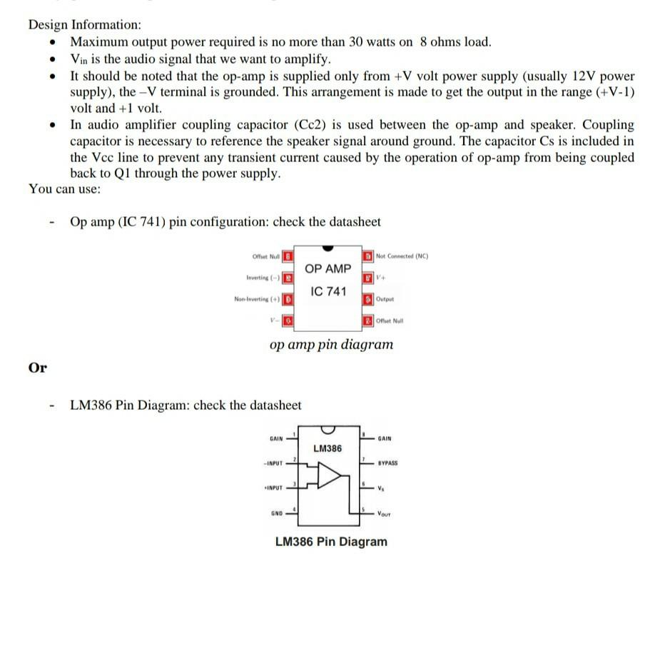
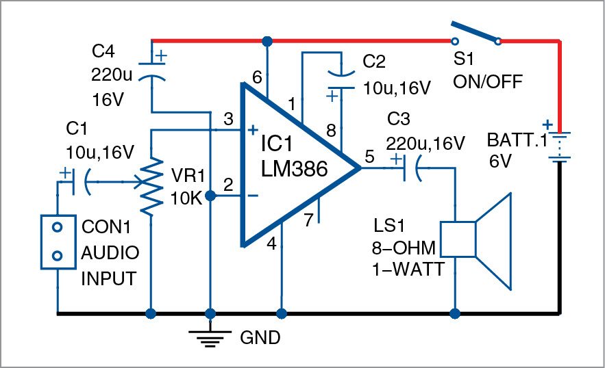
3 HiFi Audio Circuit Design 3.1 DAC Circuit Design The DAC is the source of the analog audio signal chain, and the DAC is the performance bottleneck in the chain because the THD+N performance of the best DAC in the world is 10 + dB worse than the best amplifier. The DAC contains both analog and digital functional blocks and needs ultra-low Explore a high-end audio amplifier schematic with detailed circuit diagram and component specifications. Learn about the various stages of amplification and discover the key features that make this amplifier ideal for audiophile enthusiasts. Discover the advantages of this design and how it can enhance your listening experience with its exceptional sound quality and performance. Im using your: "A GREAT SOUNDING LM386 AUDIO AMPLIFIER" circuit. The only change I made was a suggestion elsewhere to bump the capacitor from Pin 3 of the lm386 to the ground to a 50uF capacitor to help reduce more hum on the output. I am doing so to attempt to convert from 9v to 12v.
First of all, I named this amplifier Luke-The-Warm because the heat sink only barely gets warm, as opposed to a Class AB amplifier, whose heat sink can get quite hot if not actively cooled. Below you can see the schematic of the amplifier that I designed. It is based on the IRAUDAMP1 reference design by International Rectifier (Infineon). The