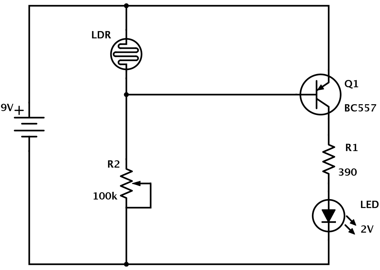
Light Dependant Resistor Circuit Circuit Diagram The LDR symbol basically represents the symbol of the resistor in electronic PCBs. However, it may describe the rays of light in the form of arrows. This way, the LDR symbol follows the same principle as the photodiode and phototransistors symbol, in which arrows illustrate the drop of light over the components. Construction Of An LDR Circuit

How The LDR Circuit Diagram Works. The LDR circuit diagram works like this: When it's dark, the LDR has high resistance. This makes the voltage at the base of the transistor too low to turn the transistor ON. Therefore, no current will go from the collector to the emitter of the transistor. All the current will instead pass through the LDR

9 Useful LDR Circuits Explained Circuit Diagram
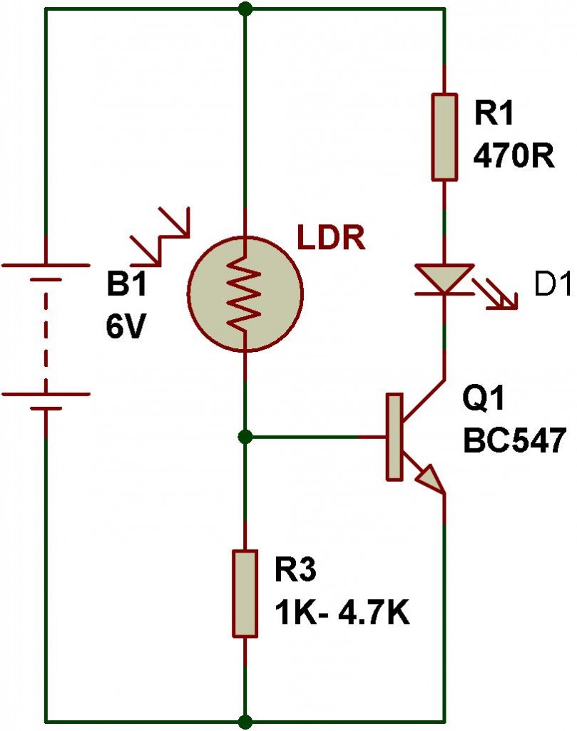
The circuit of light detector is very simple and easy to build with very few components. As you can see in the LDR circuit diagram, it can be a distinguished as two smaller circuits; a) Voltage divider made using LDR (LDR1) and a Potentiometer (RV1) b) Output (LED D1) in our switching circuit made using a transistor BC547 Q1. A Light Dependent Resistor (LDR), also known as a photoresistor, is a passive electronic component whose resistance changes based on the intensity of light it is exposed to. The resistance of an LDR decreases with increasing incident light intensity; conversely, it increases as the light intensity decreases. This circuit uses a Light

In this circuit the LDR R5, pot R6, and resistors R1 and R2 are configured with each other in the form of a Wheatstone bridge network. The op amp ICI along with the transistor Q1 and relay RY1 work like a very sensitive balance detecting switch.. The balancing point of the bridge does not get affected, regardless of variations in the supply voltage or the atmospheric temperature.
Using LDR Sensor and reading values on Serial Monitor Circuit Diagram
Welcome to Lesson 8 - Basic Arduino Course. In today's lesson, we will learn how to use an LDR sensor and read values on a Serial Monitor with Arduino.. To measure light intensity, we will use the famous and widely used low-cost LDR (Light Dependent Resistor) sensor, to detect the intensity of light or darkness easily and cheaply.. LDR (Light Dependent Resistor) Sensor A Light Dependent Resistor (LDR), also known as a photoresistor, is a type of passive electronic component that changes its resistance based on the intensity of light falling on it. Symbol of LDR. The symbol of an LDR in electronic circuits is a resistor with two arrows pointing towards it, indicating its sensitivity to light. The symbol is as